
Halo
Multi-Channel Complex Modulator
User Manual
IMPORTANT SAFETY INSTRUCTIONS
Warning - When using electronic products, these basic precautions should always be followed:
Read all the instructions before using the product.
Do not use this product near water - for example, near a bathtub, washbowl, kitchen sink, in a wet basement, or near a swimming pool or the like.
This product, in combination with an amplifier and headphones or speakers, may be capable of producing sound levels that could cause permanent hearing loss. Do not operate for a long period of time at a high volume level or at a level that is uncomfortable.
The product should be located so that its location does not interfere with its proper ventilation.
The product should be located away from heat sources such as radiators, heat registers, or other products that produce heat. No naked flame sources (such as candles, lighters, etc.) should be placed near this product. Do not operate in direct sunlight.
The product should be connected to a power supply only of the type described in the operating instructions or as marked on the product.
Care should be taken so that objects do not fall and liquids are not spilled into the enclosure through openings.
LIMITED WARRANTY
Vostok Instruments warrants this product to be free of defects in material or construction for three years from the date of purchase (invoice required).
During that period, any malfunctioning unit will be repaired, serviced, and calibrated on a return-to-factory basis, with the customer paying the transit cost to Vostok Instruments.
Malfunctions resulting from wrong power supply voltages, backward or reverse power connections, abusive treatment, removing knobs, or any other obvious user-inflict faults are not covered by this warranty, and regular rates will apply.
Vostok Instruments implies and accepts no responsibility for harm to persons or apparatus caused through the operation of this product.
The device intended for repair or replacement under warranty should be shipped in the original packaging only. Vostok Instruments can not take any responsibility for damages caused during transport. So before sending us anything, contact us at vostokinstruments@gmail.com.
INSTALLATION
Halo needs a power supply capable of providing 50mA on each of the +12V and -12V rails, and 10HP of free space in your case. We strongly recommend you to check the current consumption of your system on the ModularGrid website and your power supply capabilities before plugging in the module.
To install it, turn your case off and connect the supplied power cable to both the module and your Bus Board, minding the polarity so that the RED Stripe on the cable is oriented to the -12V line on both the module and the Bus Board. Please refer to your case manufacturers’ specifications for the location of the negative supply.
Always turn your case off before plugging and unplugging any Eurorack module.
INTRODUCTION
Halo is a compact quad LFO designed to provide a large amount of modulation in 10HP.
The module generates up to 16 simultaneous signals covering a wide range from classic triangle and square waves to complex logic-based sources.
Each channel is built on a CV-controlled analog core and offers two selectable frequency ranges, finely tuned to cover most applications.
The Logic section creates new waveforms from each channel pair using analog boolean circuits for AND, OR, and XOR operations, as well as a mix of both channels.
Halo counts with the classic Vostok design layout, making it friendly and accessible to any user, yet also deep and powerful in functionality, allowing you to create an entire array of modulation goodness in a compact form.
TECHNICAL SPECIFICATIONS
Size: 10HP
Current draw: +/-12V: 50mA, +5V: 0mA
Depth: 30mm (including power cable)
Input Impedance: 100kΩ
Output Impedance: 1kΩ
Freq CV Input Range: 10Vp-p
Output Voltage: 10Vp-p
OVERVIEW
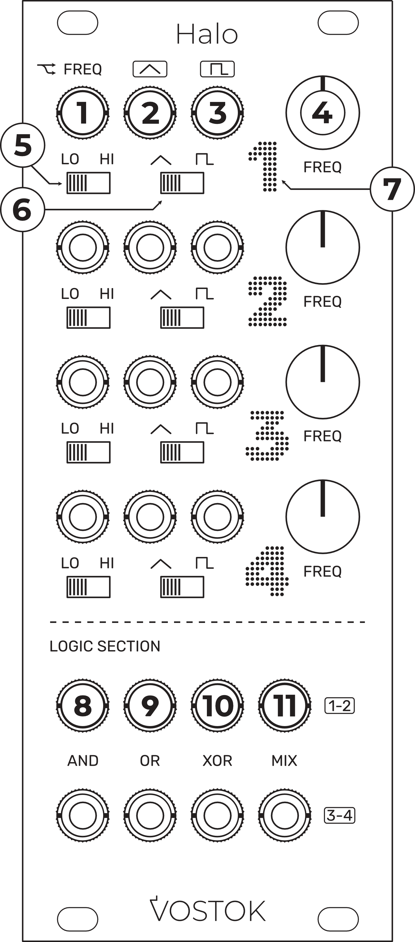
Freq CV Input: CV-control over the related channel’s frequency. The signal plugged here is daisy-chained to the right channel input. CV Range: 10Vp-p.
Triangle Signal Output.
Square Signal Output.
Freq Pot: adjust the frequency of the signal.
Frequency Range Switch: sets the operational frequency range of the related channel. LO (0,008 Hz - 8 Hz) / HI (0,08 Hz - 80Hz).
Logic Waveform Switch: selects which channel waveform will be sent to the Logic section.
LED Frequency Indicator: visual feedback over the channel’s frequency.
AND Output: output signal from the AND operation between the indicated pair of channels.
OR Output: output signal from the OR operation between the indicated pair of channels.
XOR Output: output signal from the XOR operation between the indicated pair of channels.
MIX Output: mix signal from the indicated pair of channels.
YOU CAN NEVER HAVE ENOUGH MODULATION
Move your waves
What makes a sound rich and interesting? The first thing that will probably come to our minds is something related to the frequency domain, such as its tuning, harmonic structure, or frequency response, because our hearing is very sensitive to frequency and because it is our primary way of recognizing different instruments. But there is a key part of every sound we tend to overlook when analyzing or creating our own sounds in our modular: dynamics.
If we take a one-shot sample of any acoustic instrument and analyze it with a scope to see its waveform, we will discover a quite complex dynamic structure. That dynamic complexity, generated by its physical properties and human interaction, directly modulates and shapes its frequency, timbre, and amplitude, making the sound distinctive and rich.
When working with synthesizers, one of the most interesting tools for adding movement to our waves is, by no means, LFOs. But what is an LFO? Let’s take a look at it.
LFOs 101
LFOs, or low-frequency oscillators, are oscillators that work within the lower range of the frequency spectrum, typically below the audible range. LFOs are commonly used as modulation sources to control the various parameters of our modules and add motion.
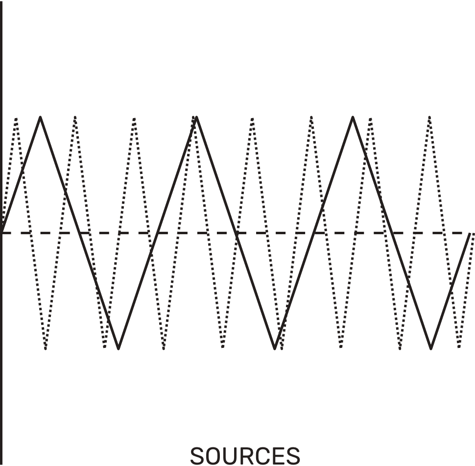
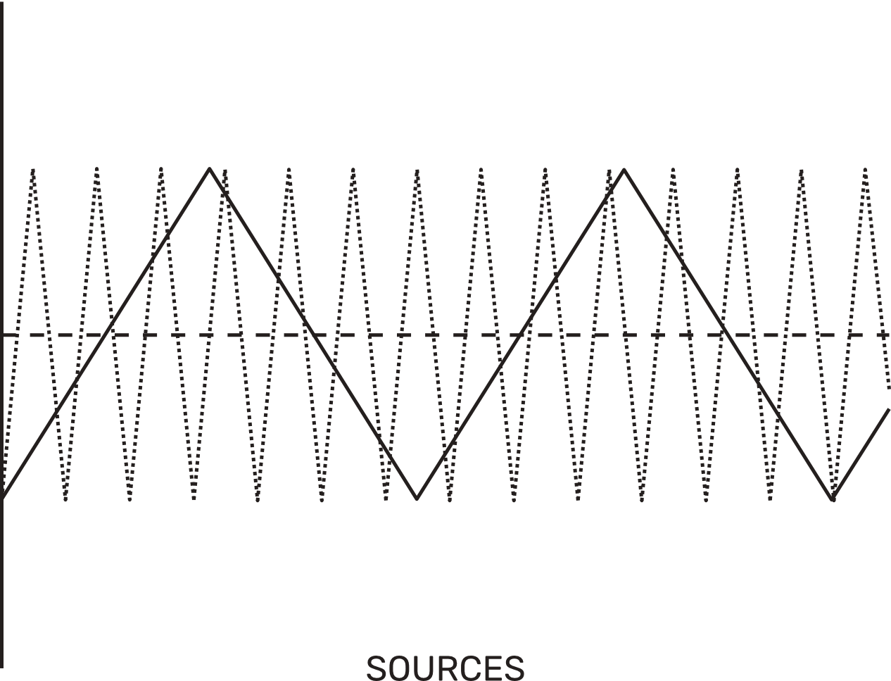
Their amplitude is usually the same as that of a regular VCO, producing symmetric bipolar signals. While LFOs can have a variety of waveforms, we decided to build our module on two of the most basic modulation waveforms: Triangle and Square.
In Halo, each channel outputs simultaneous, phase-aligned triangle and Square wave outputs with a 10Vp-p (+/- 5V) signal level.
The Triangle waveform provides smooth, linear voltage transitions, while the Square switches between its maximum and minimum states. Both are among the most straightforward and useful signals for modulating parameters and serve as a perfect foundation for creating more complex signals.
USING LOGIC WITH LFOs
A brief introduction to Logic
Logic circuits are an amazing way to create more interesting signals, and they work pretty well for modulation duties. While they can seem difficult to understand, logic circuits are quite simple and require very little effort to extract unique signals that otherwise would be much harder to obtain.
Any logic circuit typically has two inputs and one output. The output extracts the result of a concrete operation between those two signals, creating a new one that is directly related to them. This is extremely useful for adding a big layer of cohesion across our modulation lanes, as the outputs of the logic circuits will always react to the motion of their seeds.
Halo has eight analog logic circuits internally routed to each pair of LFO channels, 1-2 and 3-4. Each pair counts dedicated AND, OR, XOR, and MIX circuits with direct result outputs at the bottom Logic Section of the module. We can choose which of the two available waveforms to send to the logic circuits by using the waveform selection switch of each channel.
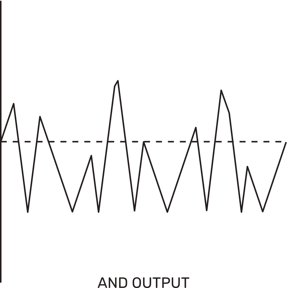
AND Function
The AND circuit compares two signals and outputs the lowest value between them. In other words, the output will always follow whichever signal is closer to its minimum state.
Since the output can never exceed the lower of the two inputs, the AND operation naturally creates dips and valleys whenever one of the channels drops, producing signals with more pronounced downward movement.
This makes AND particularly useful when we want our modulation to stay contained or pull back more often than it pushes forward.
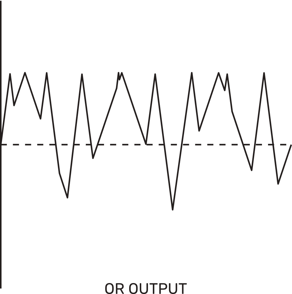
OR Function
The OR circuit is the counterpart of AND. It compares two signals and outputs the highest value between them. The output will always follow whichever signal is closer to its maximum state.
Since the output can never be lower than the higher of the two inputs, the OR operation naturally creates peaks and plateaus whenever one channel rises, producing signals with more pronounced upward movement.
When combining two square waves at different frequencies, the OR output produces a new square wave that is low only when both sources are low, resulting in longer, wider pulses.
XOR Function
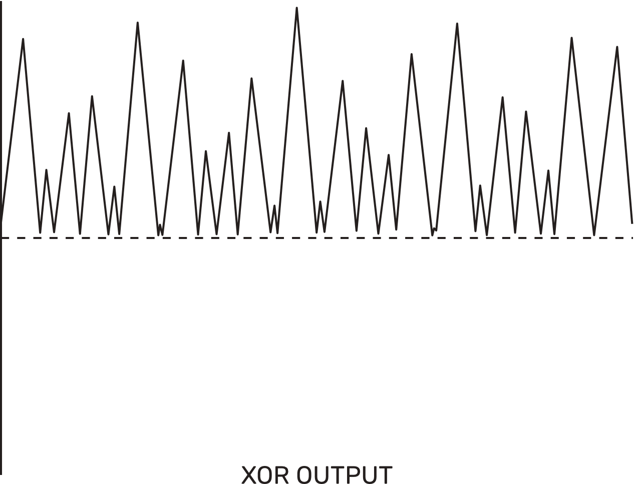
The XOR circuit, or exclusive OR, outputs a high value when the two input signals differ and a low value when they are similar. The greater the difference between the two inputs, the higher the output.
In Halo, the XOR operation is derived by subtracting the AND signal from the OR signal using a differential amplifier. This means that the XOR output is always a positive voltage, ranging from 0V to its maximum, rather than a bipolar signal.
When using XOR with two LFO signals, the result is a waveform that is more complex and unpredictable than what AND or OR produces. Since the output reacts to the difference between the two channels, XOR naturally creates signals with more movement and variation, especially when the input frequencies are not related to each other.
This makes XOR particularly useful when we want modulation that feels organic and evolving.
MIX Function
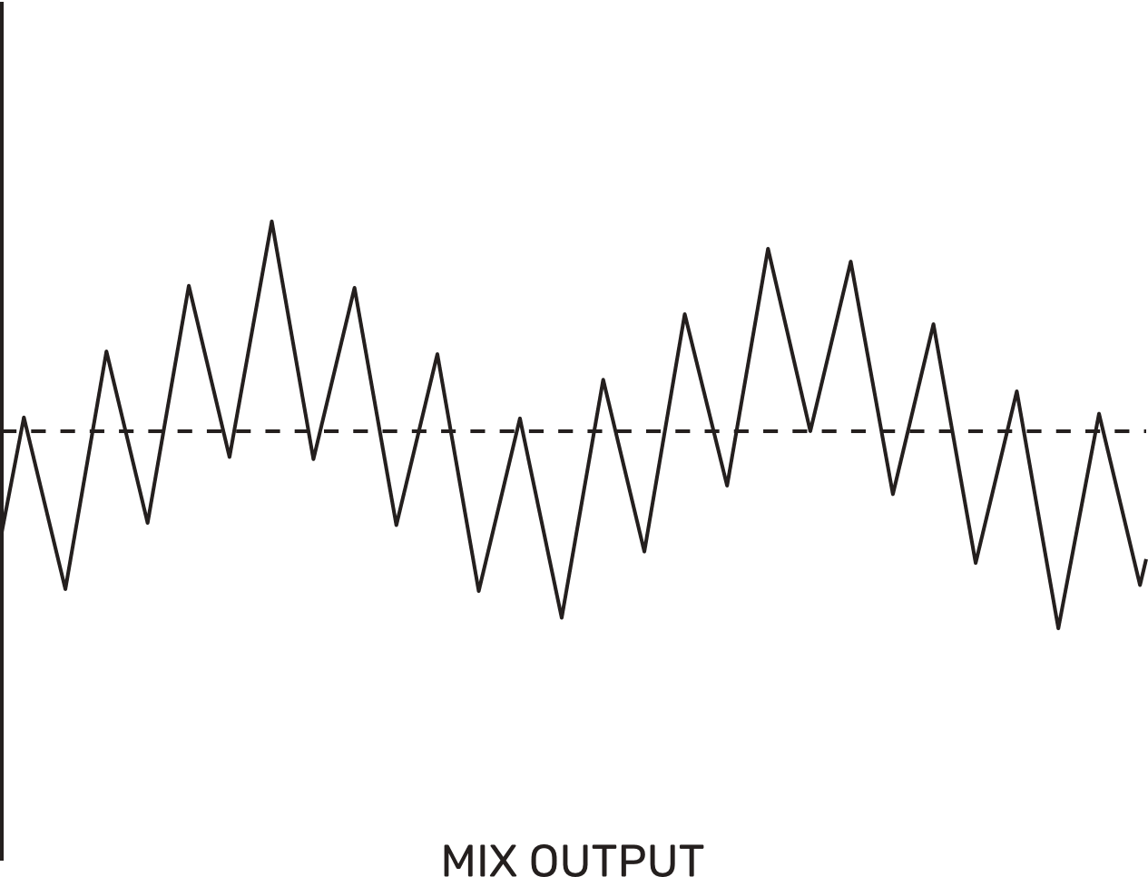
The MIX circuit combines both channels of a pair into a single output by summing their signals together. Unlike the logic operations, which compare and extract relationships between the two inputs, the MIX simply adds them, producing a signal that contains the character of both sources blended into one.
The result is a waveform that carries the movement of both channels simultaneously. If both channels share similar frequencies, the mix will reinforce their shapes. As the frequencies drift apart, the mix becomes more complex, with layered motion that can be very expressive.
FUNCTIONAL MAP
Freq Controls
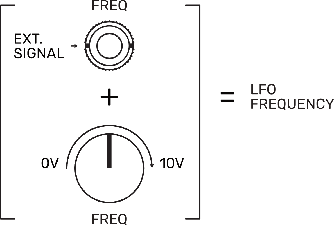
On Halo channels, the frequency is controlled by a positive voltage. The relationship between voltage and frequency is directly proportional, meaning that our signal travels from left to right, with left = 0V and right = 10V. The FREQ controls on our channels adjust the frequency by applying different positive voltages.
For the CV Inputs (FREQ Inputs), each applied voltage is added to the voltage set by the FREQ controls. If we send a negative voltage to the input, it will be subtracted from the input voltage, and the frequency will decrease. If the negative voltage applied is higher than the current value, the frequency will remain at its lowest value until the voltage at its CV Input goes above zero, at which point it will start rising again.
Range Selectors
Each channel features a two-position switch that sets its operational frequency range. The LO range spans 0.008 Hz to 8 Hz, providing cycles from over two minutes to the typical LFO territory.
The HI range covers from 0.08 Hz to 80 Hz, extending into the lower end of the audible spectrum, opening the door to audio-rate modulation effects like vibrato, tremolo, or even rough timbral textures when pushed to its upper limit.
Logic Waveform Selectors
The second switch of each channel selects which waveform is sent to the Logic section. This allows us to choose between the triangle or the square output of each channel as the source for the AND, OR, XOR, and MIX circuits.
A simple flip of this switch can drastically change the behavior of the entire Logic section, making it an easy way to explore new modulation textures on the fly.