Hive
Quad Stereo Automated Mixer
User Manual
IMPORTANT SAFETY INSTRUCTIONS
Warning - When using electronic products, these basic precautions should always be followed:
Read all the instructions before using the product.
Do not use this product near water - for example, near a bathtub, washbowl, kitchen sink, in a wet basement, or near a swimming pool or the like.
This product, in combination with an amplifier and headphones or speakers, may be capable of producing sound levels that could cause permanent hearing loss. Do not operate for a long period of time at a high volume level or at a level that is uncomfortable.
The product should be located so that its location does not interfere with its proper ventilation.
The product should be located away from heat sources such as radiators, heat registers, or other products that produce heat. No naked flame sources (such as candles, lighters, etc.) should be placed near this product. Do not operate in direct sunlight.
The product should be connected to a power supply only of the type described in the operating instructions or as marked on the product.
Care should be taken so that objects do not fall and liquids are not spilled into the enclosure through openings.
LIMITED WARRANTY
Vostok Instruments warrants this product to be free of defects in material or construction for three years from the date of purchase (invoice required).
During that period, any malfunctioning unit will be repaired, serviced, and calibrated on a return-to-factory basis, with the customer paying the transit cost to Vostok Instruments.
Malfunctions resulting from wrong power supply voltages, backward or reverse power connections, abusive treatment, removing knobs, or any other obvious user-inflict faults are not covered by this warranty, and regular rates will apply.
Vostok Instruments implies and accepts no responsibility for harm to persons or apparatus caused through the operation of this product.
The device intended for repair or replacement under warranty should be shipped in the original packaging only. Vostok Instruments can not take any responsibility for damages caused during transport. So before sending us anything, contact us at vostokinstruments@gmail.com.
INSTALLATION
Hive needs a power supply capable of providing 120mA on each of the +12V and -12V rails, and 10HP of free space in your case. We strongly recommend you to check the current consumption of your system on the ModularGrid website and your power supply capabilities before plugging in the module.
To install it, turn your case off and connect the supplied power cable to both the module and your Bus Board, minding the polarity so that the RED Stripe on the cable is oriented to the -12V line on both the module and the Bus Board. Please refer to your case manufacturers’ specifications for the location of the negative supply.
Always turn your case off before plugging and unplugging any Eurorack module.
INTRODUCTION
Hive is our take inside the spectrum of Eurorack mixers. At its core, it is a four-channel stereo mixer with CV-controlled panning per channel, but like any other Vostok module, Hive comes with several quirks that make it a handy module for every system.
Each channel can boost incoming signals to perfectly match the level of your different modules, as well as bring pro-line level devices, such as desktop synthesizers or drum machines, into your rack.
The panning works with a custom panning-law slope of -1.5dB attenuation at the center position, ensuring smooth balance transitions either manually or with CV.
Several modules can be chained together using the dedicated connectors located at the back, allowing the use of other Hive modules as channel expansions or submixes.
Hive packs a bunch of useful features into a compact 10HP layout, making it a perfect stereo mangler, FX sub-mix system, end-of-the-line mixer, and much more.
TECHNICAL SPECIFICATIONS
Size: 10HP
Current draw: +/-12V: 120mA, +5V: 0mA
Depth: 35mm (including power cable)
Input Impedance: 51kΩ (Audio Inputs), 100kΩ (CV Inputs)
Output Impedance: 510Ω
Pan CV Input Range: 5Vp-p
Pan Law: -1.5dB at center position
AC-Coupling Filter Cutoff Frequency: 10Hz
Noise Floor: -84dBV (All channels at unity gain position and panned full left. Master control at max. position)
SNR: 96dB (3.5Vrms / 1 Khz signal with channel at unity gain and panned full left. Master control at max. position)
THD+N: 0,28% (3.5Vrms / 1 Khz signal with channel at unity gain and panned full left. Master control at max. position)
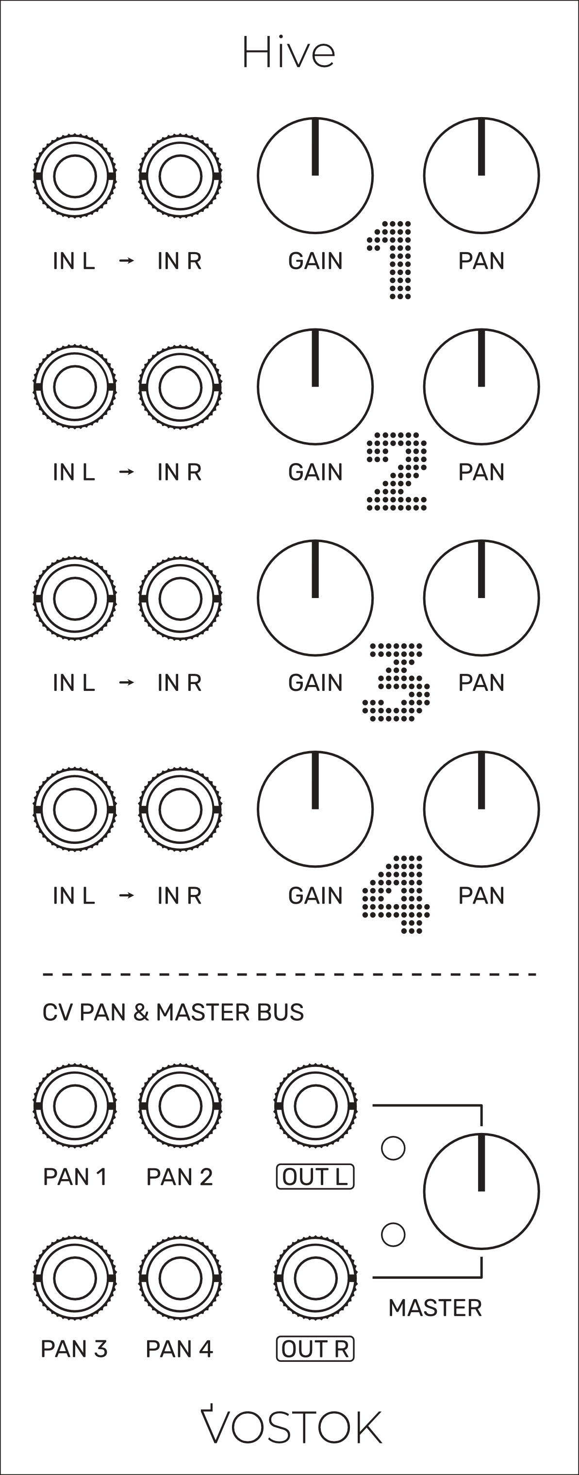
OVERVIEW
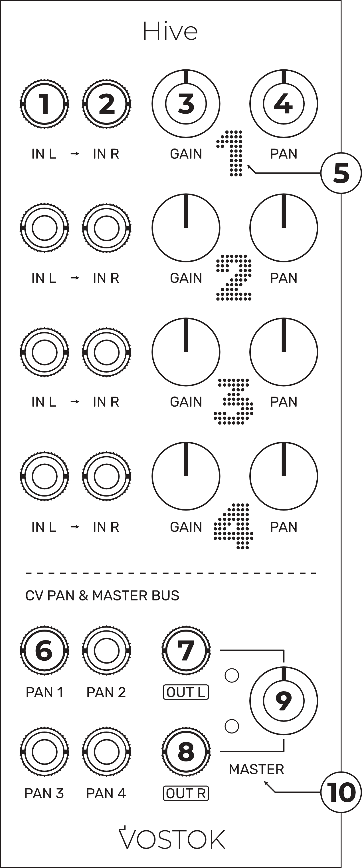
Left Signal Input: the signal plugged here is daisy-chained to the right channel input. AC-Coupled.
Right Signal Input: AC-Coupled.
Gain Pot: provides control over the signal amplitude. This control applies a maximum gain of +9dB to the incoming signal.
Pan Pot: adjust the stereo position of the signal.
LED Signal Indicator: visual feedback of both the signal amplitude and pan of the channel. White: Left, Orange: Right.
Pan CV Input: CV-control over the related channel’s Pan. CV Range: 5Vp-p.
Left Output: Unbalanced.
Right Output: Unbalanced.
Master Pot: manual control over the volume of the entire mix.
High-Level Signal LED Indicators: visual warning when the mix surpasses a threshold of approx. 17Vp-p (+/-8.5V)
STEREO TERMINOLOGY & PANNING LAWS
Pan vs. Balance
One of the most common points of confusion among users when talking about stereo is the difference between Pan and Balance and why Pan is used for Mono channels and Balance for Stereo.
As we all know, the main difference between a Mono and Stereo signal is that while a Mono signal carries only one channel, a Stereo signal counts with two independent channels (L & R). As we usually have two speakers, in order to listen to a Mono signal perfectly centered, we need to send that signal to both speakers at the same level. By adjusting the amount of signal sent to each speaker, we can alter its position on the stereo field (PAN). So basically, when we talk about "panning," we assume that portions of the same signal will be present in both channels.
In Stereo signals, otherwise, we have independent content for L & R channels, and each speaker receives and reproduces only one of the two L & R signals. If we adjust the level of one of the two channels, we will alter the "Balance" between them and give more presence to the content of one channel over the other. Unlike what happens with Pan, in a Balance control, the content of the left channel never feeds into the right one and vice versa. So, how does all this work in Hive, and which of those terms apply to our channels? Short answer: both.
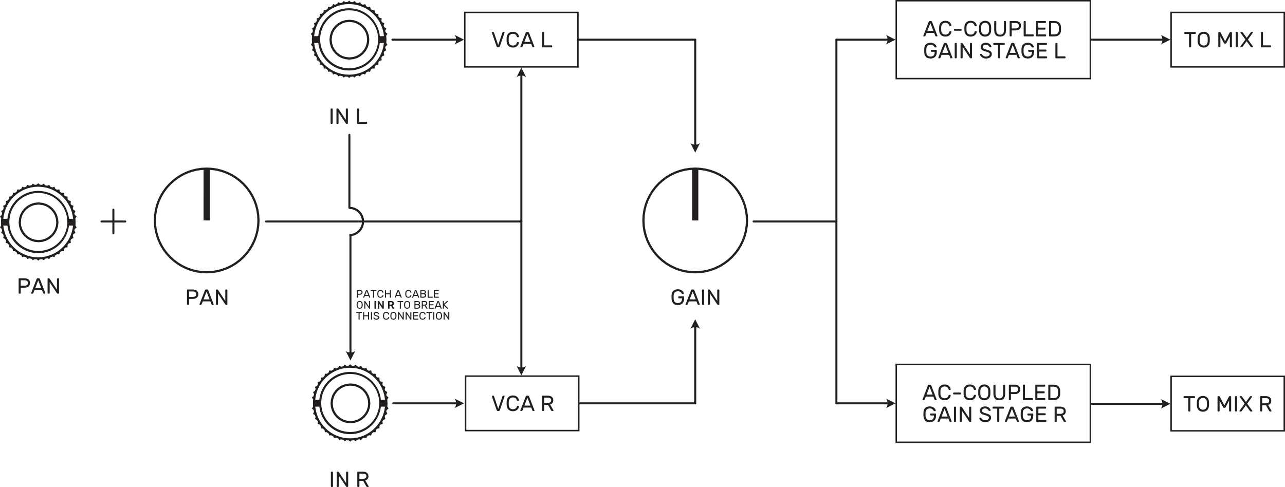
Hive channels are fully stereo and count with independent VCAs and amplification stages for both L and R signal paths. The Pan pot acts as a Balance control when a stereo signal is plugged in. Still, if we use a mono signal instead and plug it into the L input, it will be internally normalized to the R input, feeding both the L and R channels with the same signal, and turning our Pan pot into an actual panning control.
The "Center" problem
When we listen through a stereo system, we have three main reference points to identify the position of a sound in the stereo field: Left, Right, and Center. But a stereo signal only has two independent channels (L & R), so what we hear as "the center" is a creation of our brain when the information received from the L and R channels are almost identical.
In an ideal scenario, when we place a Mono signal in the stereo field through our Pan control, we would expect its loudness to remain constant, no matter where we place it. However, when we adjust the Balance control on a stereo signal, i.e., to the right, we don't expect the right channel to be louder than it was, but rather the left channel to be quieter.
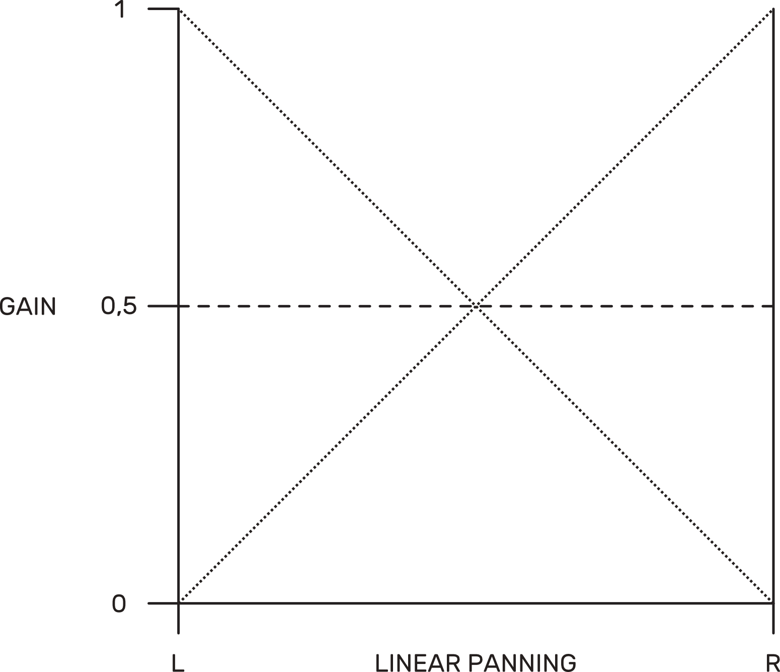
In theory, this would be easily achievable by designing the Pan control to adjust the amplitude of both L and R channels linearly with an inverse correlation so, for example, at the left position, the left channel would keep its maximum amplitude (let's call it 1) and the right channel would be silent (0). As we turn our Pan control to the center, the amplitude of the left channel would start decreasing, and the right channel amplitude would rise in direct proportion to the left channel loss. Once we reach the center position of the Pan control, both channels would have an amplitude of 0.5, summing a total amplitude of 1, so we should not have perceived any volume change, right?
Well, that's not the case, and the main reason is that amplitude and loudness are not the same thing. While the amplitude of a signal is a physical concept, loudness is a perceptual one, as the human ear's sensitivity to sound varies with frequency. We also need to consider the environment, as we are receiving sound information through the air, and all the physical agents present in the room will alter the phase, frequency, and amplitude of our signal.
For the example above to work, we need to be able to listen to our signal with a perfectly matched phase between L and R channels and in a reflection-free environment. In a real-world scenario, the phase difference between the channels causes a dip in the center of approx. -3dB when using a linear Pan control as each channel is attenuated by 6dB (half of its amplitude) at the center position. To keep an equal loudness among the whole range, we need to find a way to compensate for that center loss, and here is where the panning laws take action.
Panning Laws
The panning laws are different methods to adjust the volume of the Left and Right channels to compensate for the loudness loss that occurs in the Center when using a linear function, as in the example above (Linear Panning). Most of them imply the use of a different function slope that allows the rise of the intersection point between both channels and compensates for that loss.
One of the most famous ones is the Constant Power Panning law, which uses a sine/cosine function where both channels concur at the Center with only 3dB of attenuation. This method eliminates the dip in the Center as the sum of both channels at the Center now results in 0 dB or unity gain and a "constant power" correlation between the side channels and the Center.
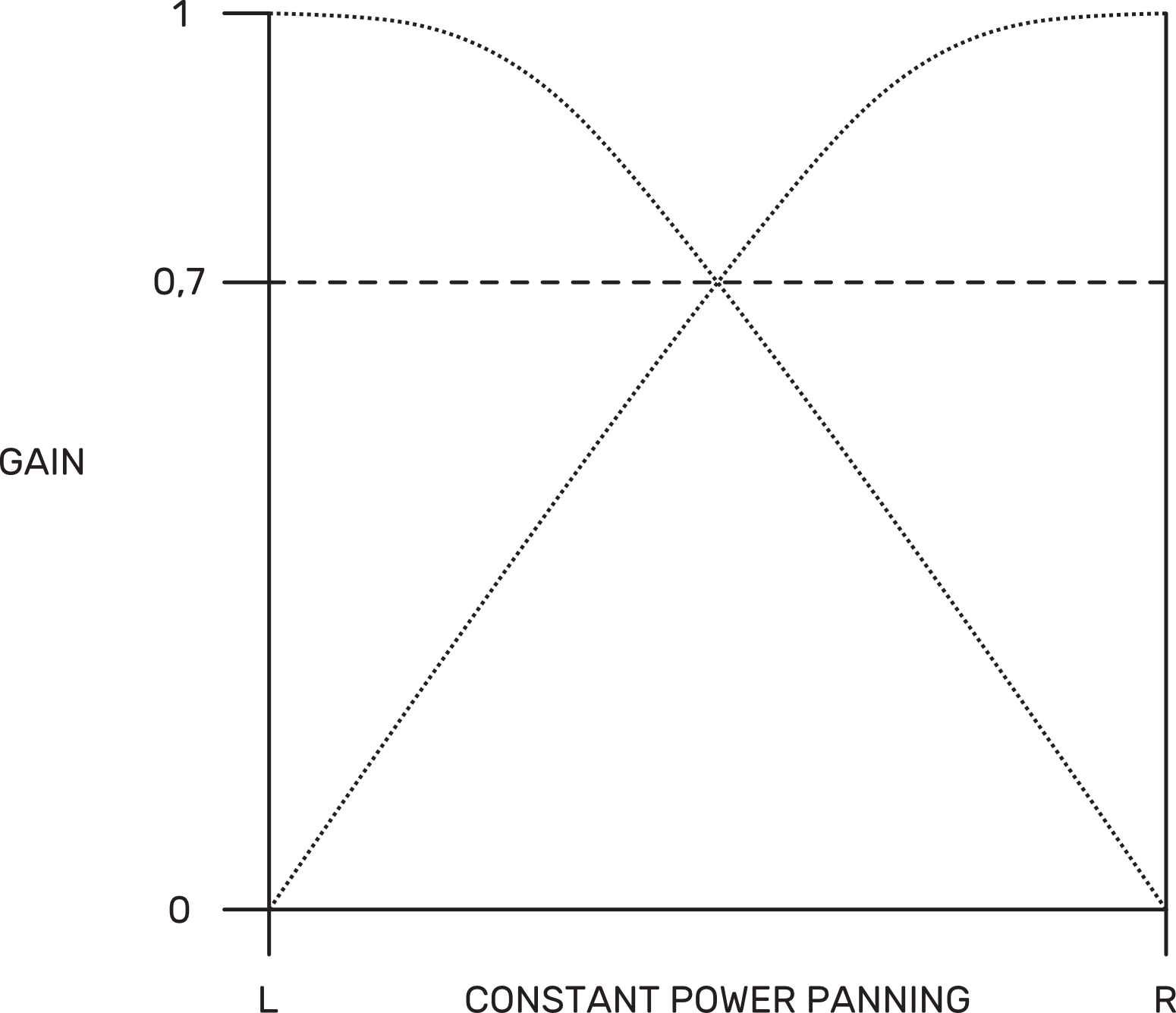
The drawback of using this method is that it collapses with the perceptual concept of loudness and its physical implications. As we are boosting the center position, if we move around the room, there will be sweet spots where the phase of the sound will be aligned and boost the Center by 3dB compared to the sides.
As you probably have concluded already, there is no perfect solution to this problem, and all we can do is make compromises. In Hive, we relied on a third method, which is actually a compromise between the previous two: the -4.5 dB law. This panning law is achieved by taking the square root of the product of both the Linear and Constant Power law, which gives us a middle ground boost where the sides channels now sum to a -1.5dB of center attenuation.
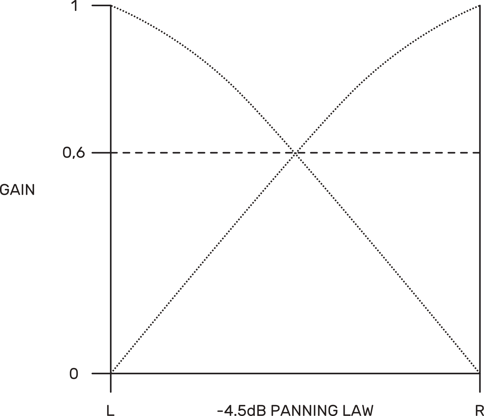
We consider this to be the best compromise, offering the least impact in our listening on all kinds of situations.
Note: Due to the analog nature of Hive and the presence of VCA's, among many other components in the audio path, you can expect a deviation of around +/-0.5dB from the target.
AC-COUPLED STAGES
About AC & DC-Coupling
In our modular synthesizers, we have several types of signals (Audio, V/Oct, Gate, Clock, etc.). While each of those signals has different purposes, we can group all of them into two main technical categories: AC and DC signals.
In the real world, we call an AC Signal any signal whose voltage varies continuously with time, like an audio signal, and a DC Signal a signal of constant non-zero voltage value, like a V/Oct signal. However, most of the signals we use in Eurorack, such as the V/Oct, could be considered AC, as their voltage, although not as fast as in an audio signal, also changes over time. So, what do we do?
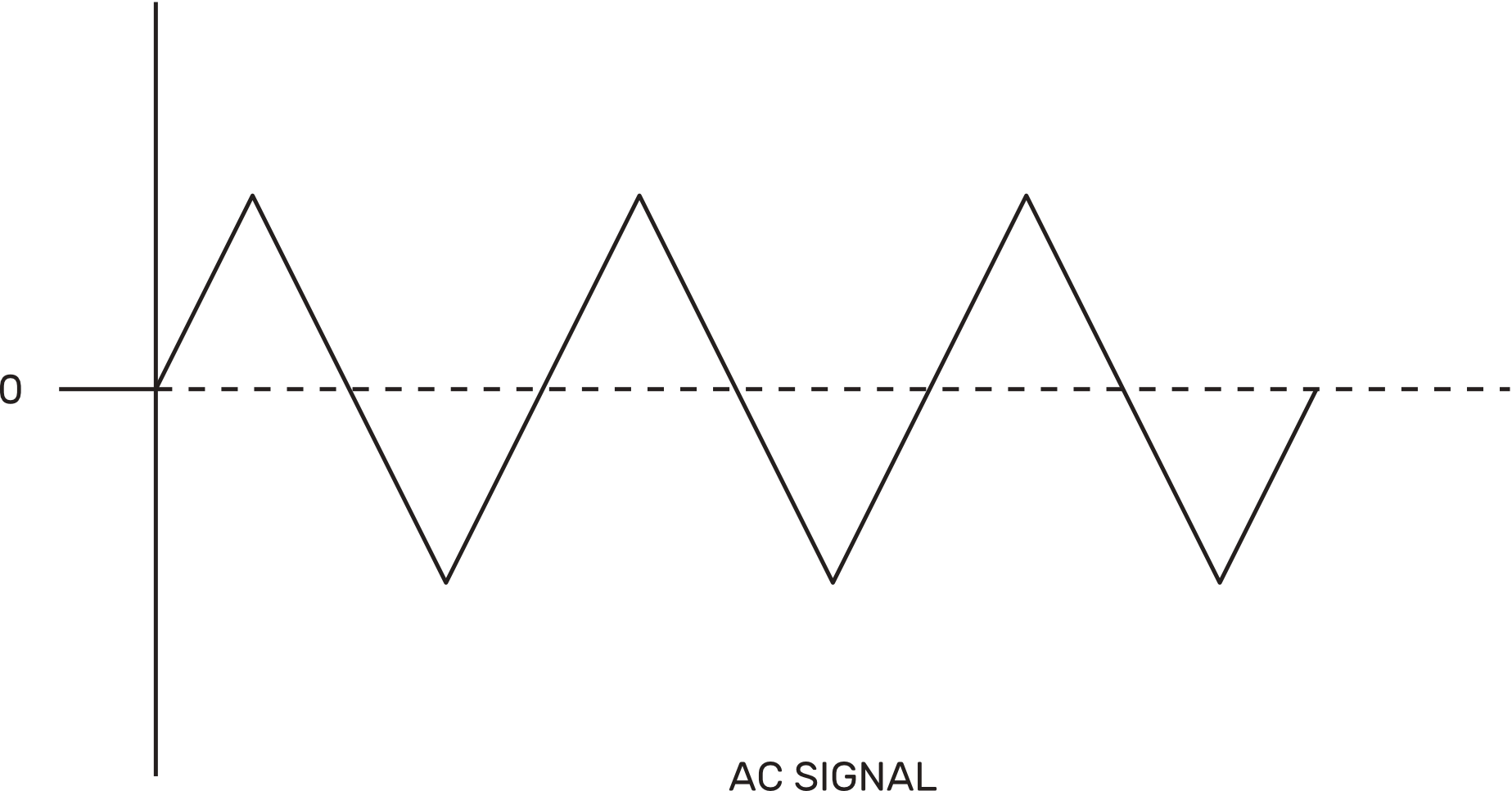

When we design our modules, we can decide if we want our circuits to work with both AC and DC Signals by basically letting any signal passing through (DC Coupling) or, like in our case, limiting the circuit to work exclusively with AC Signals by blocking any DC component with a high-pass filter (AC Coupling).
In the audio realm, DC signals are unwelcome. They are the root of many problems like a reduction of the overall headroom when mixed with our audio signal and potential asymmetrical clipping, and they also induce rustling noises when passing through potentiometers
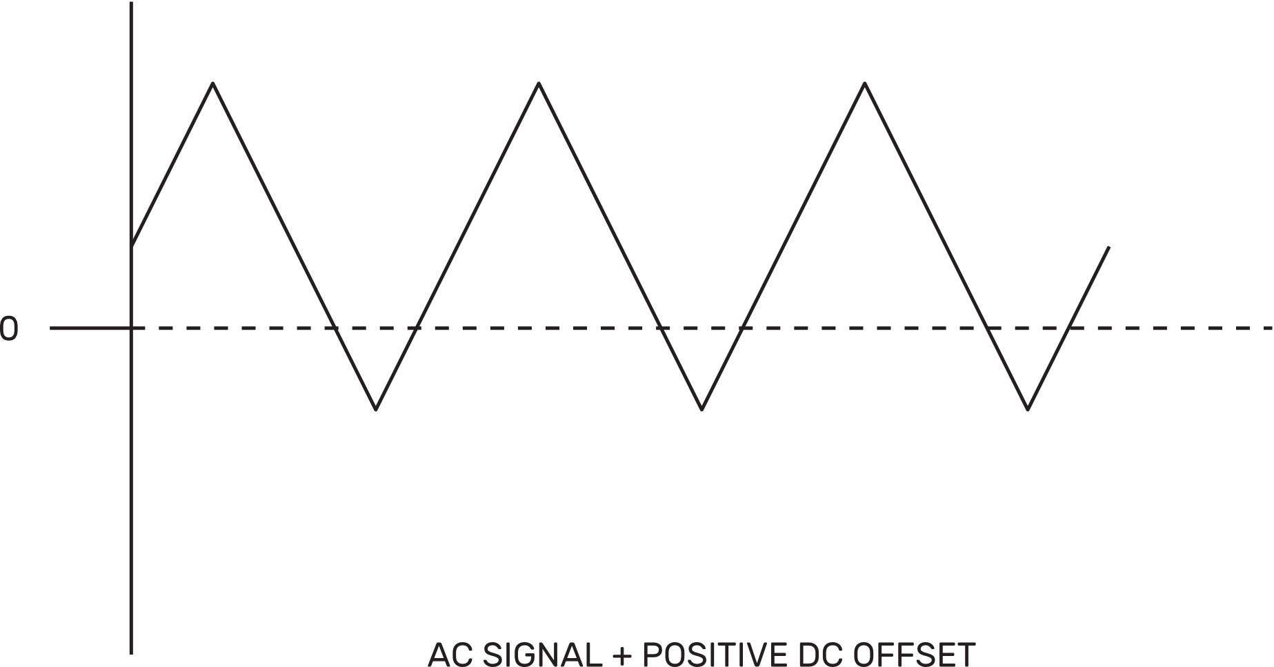
In Hive, each channel comes with a high-grade AC Coupling filter that attenuates signals below 10hz. The filter features high-grade Polypropylene audio capacitors carefully positioned near each Gain pot to minimize the typical rustling noise from stereo potentiometers when a DC bias current passes through the pot wiper.
FUNCTIONAL MAP
Gain Controls
The Gain control on each Hive channel adjusts the level of the signal from 0 (fully counterclockwise position) to a maximum of +9dB over the input signal amplitude (fully clockwise position). It allows the boost of line-level signals from external devices to modular levels. Be aware that to boost your device to nominal modular levels (10Vp-p/3.5Vrms), its output should provide a signal of at least +4dBU (3.5Vp-p/1.22Vrms).
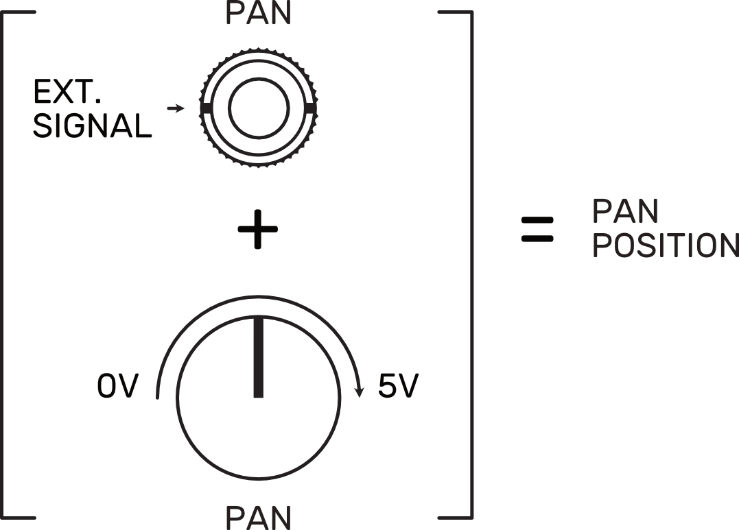
Pan Controls
On Hive channels, the panning is controlled by a positive voltage. The relation between voltage and panning is directly proportional, which means that our signal travels from left to right, being left = 0V and right = 5V. The PAN controls of our channels are adjusting the panning by applying different values of positive voltage.
On the CV Inputs (PAN Inputs), every voltage applied is summed to the voltage value set by the PAN controls. If we send a negative voltage to the input, it will be subtracted from that voltage value, and the channel will go to the left. If the negative voltage applied is higher than the current value, the channel will remain in the left position until the voltage at its CV Input goes above zero, at which point it will start traveling again.
Master Section
Hive counts with a little master section at the bottom composed of a master control and two high-level warning LEDs for both L and R channels of the master mix. These LEDs light up when the master mix surpasses a threshold of 17Vp-p (+/-8.5V). As Hive channels have an approximate headroom of 22Vp-p (+/- 11V), the activity of the high-level LEDs doesn't necessarily mean that the master is clipping, but rather that you should keep an eye on your levels and adjust the master control if necessary.
Chaining Ports
Several Hive units can be chained to work as a bigger submix system and expand their channels by using the two auxiliary ports located at the back of each module. These ports, labeled as "Chain In" and "Chain Out," are used to send the main mix of one module to another. To do that, use the provided 2x3 ribbon cable connecting the "Chain Out" of the module that sends its mix to the "Chain In" of the module that receives it. By plugging a patch cable into any of the outputs of the sender module, the internal chain breaks, and the output is redirected through the patch cable.
DISCLAIMER: The Chain ports located at the back of Hive are only compatible with other Hive units. Don't connect them to other modules to avoid any possible damage.