
Sena
Multi Channel Sound Source
User Manual
LIMITED WARRANTY
Vostok Instruments warrants this product to be free of defects in material or construction for three years from the date of purchase (invoice required).
During that period, any malfunctioning unit will be repaired, serviced, and calibrated on a return-to-factory basis, with the customer paying the transit cost to Vostok Instruments.
Malfunctions resulting from wrong power supply voltages, backward or reverse power connections, abusive treatment, removing knobs, or any other obvious user-inflict faults are not covered by this warranty, and regular rates will apply.
Vostok Instruments implies and accepts no responsibility for harm to persons or apparatus caused through the operation of this product.
The device intended for repair or replacement under warranty should be shipped in the original packaging only. Vostok Instruments can not take any responsibility for damages caused during transport. So before sending us anything, contact us at vostokinstruments@gmail.com.
INSTALLATION
Sena needs a power supply capable of providing 130mA on each of the +12V and -12V rails, and 14HP of free space in your case. We strongly recommend you to check the current consumption of your system on the ModularGrid website and your power supply capabilities before plugging in the module.
To install it, turn your case off and connect the supplied power cable to both the module and your Bus Board, minding the polarity so that the RED Stripe on the cable is oriented to the -12V line on both the module and the Bus Board. Please refer to your case manufacturers’ specifications for the location of the negative supply.
Always turn your case off before plugging and unplugging any Eurorack module.
INTRODUCTION
VCOs are probably the most popular modules in the Eurorack world.
At its most common form, an oscillator module creates different basic waveforms by shaping its core, which gives us several timbres sharing the same frequency.
On Sena, we decided to reorganize those principles. We have the basic waveforms as on any VCO, but each has an independent core and frequency control. In addition, the tuning inputs of each channel are daisy-chained, allowing to create easy transpositions or detuning between them.
To maximize stability and tracking accuracy, every channel is designed around the famous 3340 oscillator core, present in many legendary synths like the Roland SH-101 and Jupiter-6, Oberheim OB-Xa, and the Sequential Prophet-5.
On top of that, the module counts with four dedicated CV-controlled Modifiers to extend the timbral range of each core: a two-stage Folder for the Sine, a Trapezoid shaper for the Triangle, a Phase modulator for the Saw, and a half-range Pulse-width modulator for the Square.
The addition of a complete analog Noise Bank makes Sena a super powerful and compact sound source. A cornerstone for any Eurorack setup.
TECHNICAL SPECIFICATIONS
Size: 14HP
Current draw: +/-12V: 130mA, +5V: 0mA
Depth: 30mm (including power cable)
Input Impedance: 100kΩ
Output Impedance: 1kΩ
CV Inputs Range: 10Vp-p
Frequency Pot range (FINE switch disabled): ∼ 6 octaves.
Frequency Pot range (FINE switch enabled): ∼ 2 semitones.
Frequency Range in LFO mode: ∼ 0.15Hz to 10Hz
OVERVIEW

FREQ Input: CV control over the oscillator frequency. It can work as regular V/Oct or as Linear FM Input. The incoming signal is daisy-chained to the next channel. Range: 10Vp-p.
Modifier CV Input: CV control over each channel modifier. Range: 10Vp-p.
Oscillator Signal Output.
FREQ Pot: manual control over the oscillator frequency. The range of this pot can be set with the FINE switch.
Modifier Pot: manual control for each channel modifier.
V/O - FM: selects between the two operational modes of FREQ input. Left: V/Oct. Right: Linear FM.
FINE: adjust the operational tuning range of the FREQ Pot. Left: six octaves. Right: two semitones.
LED Frequency indicator.
VCO/LFO: sets the frequency range of the oscillator to work as VCO or LFO.
Noise Bank Signal Outputs.
GETTING STARTED
Sena is laid out in five channels of sound generation. The first four are composed of a VCO and a dedicated waveform modifier, and the fifth is a compendium of four noise generators.
Channels 1-4 are identical in functionality, with symmetrical features between them, but entirely different in terms of sound. As those features represent the functional core of Sena, let’s take a look at them first.
VCOs: FUNCTIONAL MAP
Frequency Controls
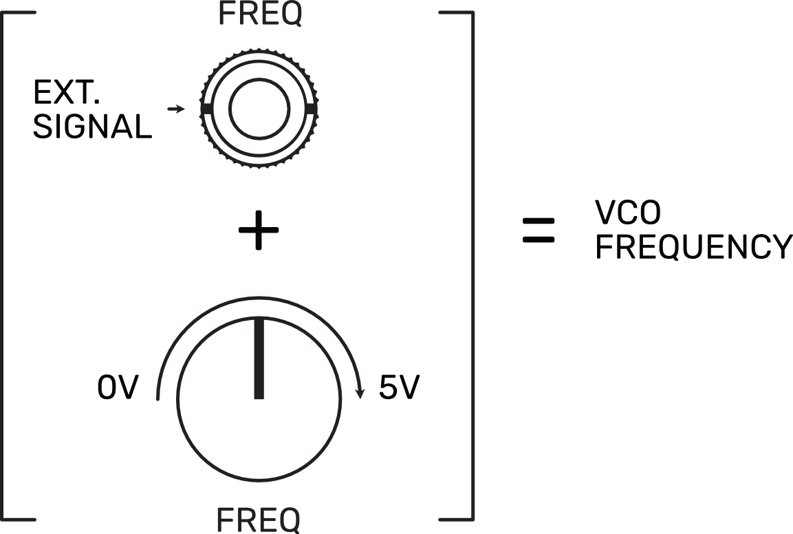
On Sena VCOs, frequency is controlled by a positive voltage. The relation between voltage and frequency is directly proportional, which means that as higher the voltage higher the frequency. The tuning controls of our VCOs (FREQ Pots) are modulating the frequency by applying different values of positive voltage. In modular synths, the frequency can also be controlled by external signals like, for example, other VCOs, which implies the presence of negative voltage.
On the CV Inputs of our oscillators (FREQ Inputs), every voltage applied is summed to the current-voltage value set by the tuning controls. If we send a negative voltage to the input, it will be subtracted from the current-voltage value, and the oscillator will slow down. If the negative voltage applied is higher than the current value, the oscillator will stop and wait till the voltage at its CV Input goes above zero to start oscillating again.
FINE Mode
Each channel FREQ Pot has two ranges of operation selected with the FINE switch. When it's disabled (left), the FREQ pot works over a range of 6 octaves. When it's enabled (right), the FREQ pot range goes down to 2 semitones.
Both ranges have musical approaches in mind. While the default mode lets you apply heavy transpositions to the pitch, FINE offers tons of precision to match the tuning of our VCO accurately.
Be aware that as the VCO frequency comes from the sum of the voltages present either at the FREQ Input and the FREQ Pot, with nothing at the FREQ Input and the FINE switch enabled, the oscillator will be running at its initial frequency.
Frequency Modulation Modes: V/O - FM
Sena FREQ Inputs work in two operational modes: V/Oct and Linear FM, selected with the V/O - FM switch located below the input.
In V/O the VCO frequency is modulated following a precise V/Oct exponential function. Each oscillator core offers accurate and stable tuning over 8 octaves when the V/O mode is active.
In FM mode, the incoming signal will follow a linear response. This mode is perfect for high-frequency modulation patches. Note that as audio rate signals are expected here, the input turns AC Coupled when the FM mode is selected.
Daisy-Chain Operation
By default, Sena sends the signal present at each FREQ Input to the next one. Each end of the chain has a buffer circuit to keep the voltage accurate. To break the chain, patch a cable on the desired input. This implementation makes the creation of polyphonic patches easier.
LFO Mode
Sena is also a superb multi-channel modulation source thanks to the LFO mode implemented on each of its VCOs. To activate it, just set the VCO - LFO switch of the desired channel on the LFO position. In this mode, the frequency range of the core runs down with a minimum and maximum frequency of 0.15 to 10 Hertz.
VCOs: TIMBRAL ANALYSIS
One of the best features of Sena is the timbral diversity of its channels. Sena allows one to control the frequency of each waveform independently and to manipulate its harmonic content, expanding the sonic possibilities of the module massively.
This is possible with the implementation of a dedicated CV-controlled waveform modifier on each channel. Each modifier is unique and has been designed with waveform timbral capabilities in mind and following musical approaches. Let’s take a look at them.
Channel 1: Folding Sine Wave
In electronic music, the sine wave represents the starting point of every sound. Composed of only one harmonic, it is the core of the primary synthesis technique: Additive Synthesis. Its lack of harmonics makes it ideal for bass and kick drum sounds where we want to preserve a deep and rich low end (i,e 808 kick drum) and as a modulation source, being the key to effects like tremolo or chorus.
Sena’s sine wave generator counts with a two-stage wave-folder circuit (FOLD) that enlarges its potential, increasing the harmonic content.
In wave folders, once an input reaches a certain threshold, the circuit inverts the wave direction, “folding” it. As the FOLD amount increases, it’ll lower that threshold, increasing the number of times our wave gets folded.
In our circuit, the waveform folds entirely two times by adding several new harmonics during the process, morphing our initial sine wave into a much more complex waveform.
FOLD amount can also be CV controlled by applying an external signal to the FOLD Input. A 10Vp-p signal is needed to cover the whole input range. The signal present is summed to the FOLD Pot value.

Channel 2: Triangle / Trapezoid Generator
The triangle wave is another classic waveform present in almost any synthesizer. It contains only odd harmonics. The amplitude of each harmonic is inversely proportional to the square of the harmonic number, which means its energy is concentrated in the harmonics closer to its fundamental frequency, creating a soft sound similar to a sine wave.
On the other hand, trapezoid waveforms are not as usual as triangles. While both contain only odd harmonics and share the tonal proportion, the polarities of the harmonics are different. While the triangle wave alternates polarities on each odd harmonic, the trapezoid wave alternates polarities on successive pairs of odd harmonics, flattening the waveform peaks.
Both waves work pretty well as sub-oscillator for other waveforms but also as the core of bass, lead, and organ-like sounds. As modulation sources, they are fantastic on FM-style patches thanks to their linearity.
Sena’s second channel includes a CV controlled wave-shaper (SHAPE) that morphs our triangle wave into a trapezoid wave and vice versa. The circuit applies a symmetrical clipping stage to the triangle, flattening the peaks and creating interesting timbral variations during the process. In contrast with the abrasive timbres created by FOLD, the sound of SHAPE is much more subtle and sophisticated.
Same way as we saw on FOLD, SHAPE can also be CV controlled by applying external signals to SHAPE Input. A 10Vp-p signal is needed to cover the whole input range. The signal present is summed to the SHAPE Pot value.

Channel 3: Phase Shifting Saw Wave
Talk about the saw wave is talk about, probably, the most popular waveform in electronic music. Present in almost every synth, the sawtooth wave is the core of subtractive synthesis and the base of thousands of popular sounds.
With a massive harmonic content, a saw wave distributes its energy across the entire spectrum in inverse proportion to the harmonic number. As it contains both even and odd harmonics with reasonably large amplitude, the sound of the saw wave is not soft but raw, making it perfect as a starting point to create rich bass, strings, pads, and much more.
On Sena, our saw wave generator reached a new dimension with the addition of a dedicated Phase Shifting circuit (PHASE).
Based on the “Sawtooth-Driven Multi-Phase Waveform Animator” published by Bernie Hutchins in Electronotes issue 87, the circuit uses a comparator with differential amplifiers to sum a second saw wave that shifts its phase respect to the original.
As the phase shifts, the amplitude of the harmonic content changes its correlation and creates new overtones. Note that as the phase travels from 0 to 360 degrees, both saw waves are in phase at either minimum or maximum position of the PHASE pot, having a non-shifted saw wave at both extremes.
The circuit creates a pleasant moving effect when modulated by low-frequency signals such as LFOs, working pretty well with strings, pads, and any sustained sound.
To cover the whole range, a signal of 10Vp-p is needed at the PHASE Input. The signal present is summed to the PHASE Pot value.

Channel 4: Square / Pulse Wave Generator
Square and Pulse waves are probably the most common signals in any electronic device, synthesizers included.
Like the Triangle wave, the Square wave contains only odd harmonics with inversely proportional energy to its number. Their structure is quite similar, but in a Square wave, the harmonics do not roll away as soon as the ones in the triangle, and even the harmonics further from the fundamental contain a good amount of energy.
Unlike other waveforms, the amplitude of square and pulse waves only has two states, maximum and minimum. While a square wave has equal time between maximum and minimum voltage, a pulse wave is essentially a square wave with an adjustable amount of time between each cycle before the voltage drops from maximum to minimum (Pulse-Width). The percentage of time that the signal is high is known as a duty cycle.
Sena’s Pulse Width Modulation circuit covers a range from a 50% duty cycle (Square wave) to around 96% duty cycle. It travels only in the second half of the entire Pulse Width range, allowing one to have its starting point (Square wave) always at PWM Pot zero position and, to enhance its precision, being able to get narrow pulses. Users of vintage Japanese synths like Roland or Yamaha will find this PWM configuration familiar in terms of sound and feel.
Note that unlike what happens on previous modifiers, when an external signal is present at PWM Input, the PWM Pot turns into an attenuator of that signal.

ANALOG NOISE BANK
In Synthesis, noise can be creatively harnessed in many ways. It can be used to create percussion sounds such as hi-hats, cymbals, and snares, to emulate the natural sound of the wind or sea, or to mix it with other waveforms adding sonic interest to them.
Sena includes a bank with four popular noise generators: White, Pink, Brown, and Blue. The names of the different types of noise came from an analogy to visible light. This comparison is not entirely accurate, but it gives a good idea of how they are related to different spectrums of energy.
White Noise
Also referred to as Flat Noise, it is the most common form of noise. It contains every frequency, amplitude, and phase relation of a sine wave throughout the audible spectrum with equal energy distribution. Even having a flat energy distribution across all frequencies, White noise often sounds harsh and bright due to the logarithmic response of our ears.
Pink Noise
Sometimes described as “musically” flat noise, Pink noise is probably the most used noise in synthesis contexts. Compared to White noise, its spectral power density decreases by 3dB per octave, making it sound darker.
Blue Noise
Commonly thought of as the opposite of Pink noise, Blue noise has a power density of +3dB per octave, favoring higher frequencies over lower ones. Its bright and soft sound makes it perfect to be combined with other waveforms, adding clarity and brightness to them.
Brown Noise
Often referred to as Red noise, Brown noise decreases its spectral power density by 6dB per octave compared to White noise. As its energy is primarily located in the low end, Brown noise sounds even darker than Pink noise and performs better as a modulation source.